Lights, camera, action!
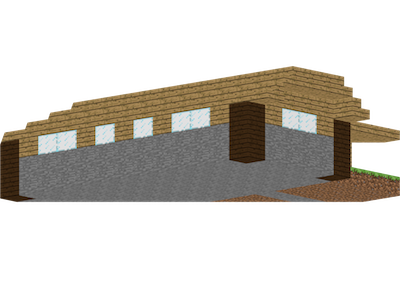
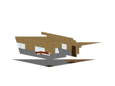
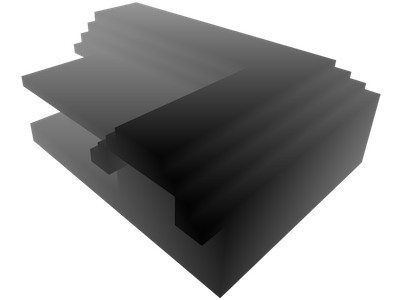
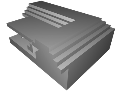
Paper Pickaxe shows the user four CG images that give a preview of what his papercraft model will look like when he finishes creating it. That way, it is clear how the program is translating the Minecraft schematic into papercraft form. Here is an example:
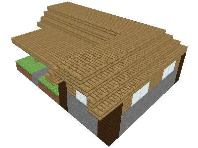
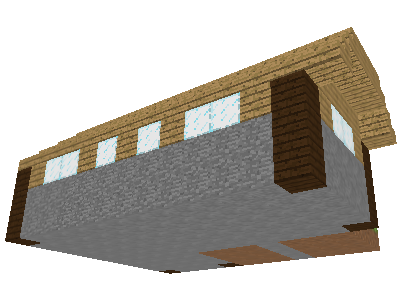
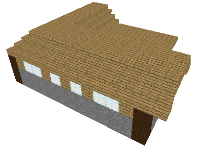
Rather than showing the model from a few preset camera angles, such as top, front, and side, the program automatically chooses the angles based on the model. Since a quick Google search did not turn up any previous work on this problem, I designed my own algorithm. My approach is to choose camera angles that maximize the visible surface area - the number of square units of the surface visible in at least one of the four images. To accomplish this, the program randomly generates a few dozen camera angles and chooses the best ones.
Selecting random camera angles
Some of the randomly selected camera angles are "outside" camera angles positioned outside the model's convex hull. To pick outside camera angles, the program computes a bounding sphere for the model. It randomly selects a camera direction, and positions the camera so that the center of the sphere is in the center of our view and the sphere fits inside the view frustum.
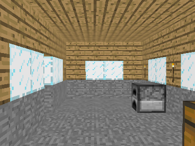
The algorithm also picks several "inside" camera angles to evaluate. An inside camera angle is positioned inside the model's convex hull, but outside the model's interior, and faces a random direction. The program limits its search to positions that are a sufficient distance from the surface of the model, in order to avoid clipping faces that are too close to the camera.
Ideally, the program would choose the positions of inside camera angles uniformly at random from all allowable positions. However, I implemented a simpler approach instead. The program uses rasterization to locate several allowable positions, and then randomly selects from the positions it found.
The program randomly selects some planes that intersect the bounding sphere, and for each plane, finds points in that plane that can function as inside camera positions. To do this, it renders the scene in an offscreen buffer using an orthographic projection, with the camera facing perpendicular to the plane. It creates three images for the plane: one for the portion of the scene at least units behind the plane, one for the portion within units, and one for the portion at least units in front of the plane, where d is the minimum allowable distance from the camera to the model in units. These are the "in layer", "mid layer", and "out layer" respsectively.
The set of valid inside camera positions in the plane is roughly equal to the intersection of the points in the in layer and the out layer, minus the points in the mid layer. More precisely, a point is a valid if it satisfies the following conditions:
- There is a face in back of it, in the in layer.
- There is a face in front of it, in the out layer.
- There are no faces near it, in the mid layer. Specifically, the mid layer should not have anything within a p × p square centered at the point, where p is the number of pixels measuring d units in length.
- The next face in front of it is a front face (as in back face culling). If the next face is a back face, then the point is in the model's interior. To check this, for the out layer, the program renders all of the faces with one color, using back face culling, then renders all of the faces with another color, using front face culling.
Note that this algorithm will miss some points that are inside the convex hull. However, for every valid inside camera position, there is some plane for which the algorithm will find it.
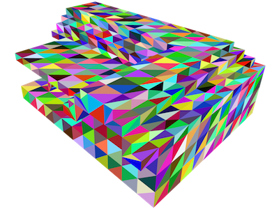
Estimating visible area
For each angle, the program computes the fraction of each face that is visible. Rather than attempt an exact solution, the program uses rasterization. It renders the scene in an offscreen buffer, using a different color for each face. It reads the z buffer, obtaining the z coordinate of each pixel. Then, it renders the scene a second time, coloring the entire model white, with a single diffuse light where the camera is positioned. The light has intensity 1, regardless of the distance.
The estimated surface area corresponding to a given pixel is given by the expression , where z is the z coordinate, n is the amount of diffuse lighting, fy is the angle of the field of view in the y direction, and h is the height of the image in pixels. Observe that the area is larger the larger the pixel's z coordinate and the more the face's normal deviates from the ray from the pixel to the camera.
At this point, I inject a slight preference for faces that are facing the camera, on the grounds that faces parallel to the camera, while visible, are more difficult to view. I achieve this preference by multiplying the above expression by , where b is the extent of the bias. (I use .)
Selecting the best camera angles
Once the program has a set of random camera angles and how much of each face is visible from each camera angle, it is in a position to pick the best four. If face visibility were an all-or-nothing proposition, then this would be the max cover problem. According to Wikipedia, "the greedy algorithm is essentially the best-possible polynomial time approximation algorithm for maximum coverage." The greedy algorithm would be to take the camera angle for which the sum of the areas of the visible faces is greatest, then to take the camera angle for which the sum of the areas of the visible faces not visible in the first angle is greatest, and so on.
However, it is possible for only a portion of a face to be visible. Thus, I implemented a variant of this using the visible surface area rather than the sum of the areas of the visible faces. If A is the area of a given face, AS is the estimated area that is visible from a set of camera angles S, and AX is the the area visible from camera angle X, then I estimate the area that is visible from camera angle X and not visible from a camera angle in S to be .
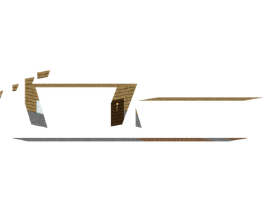
Also, I include a preference for inside camera angles, to make it clear that the papercraft model includes any "inside" parts of the model, provided they are technically on the outside surface of the model. In the example, the house's door is partway open, so the "inside" of the house is part of the model's surface.
I hope you found this article useful. If you have any suggestions or corrections, let me know in the comments.
May 30, 2016
JoshValjosh·May 14, 2025·+0
Came here from videotutorialsrock.com. The email link there seems to be broken, but that site was my intro to graphics and programming in general. Much appreciate the work that went into it and for launching me into my career some 10-15 years ago.